a special ring
# a special ring
I decided to make a special ring for my proposal to my girlfriend.
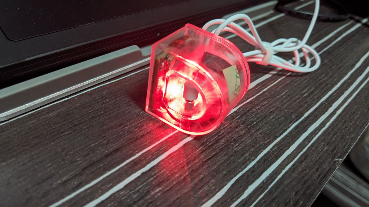
The final result:
 It boasts a STM32WB55CU microcontroller, attached to a separate Bluetooth antenna. A magnetic charging port for a 18mAh battery. And most importantly a whopping 128x128 resolution 1 bit monochrome display all encased in transparent plastic. Amazing.
Here are the planning notes I wrote down at the start of this project. You can clearly tell that i do not know…
# …what am i doing
Lets not get carried away. We need:
- THE ACTUAL FKING RING
- A PHOTOGRAPHER??
- my own ring
# Choice of display
The main advantage of electronic paper displays (EPD) is that there is no power consumption when displaying a static image.
So if we want to use it to display the time it is a lil waste as it will have to keep refreshing. More efficient to use a LCD segment display
Apparently, there is such thing as memory LCDs which are very low powered although needing constant power (the bit can retain but requires an oscillating freq to prevent the bit from getting stuck)
Does the display wrap around the whole ring? Or just a small squarish one in the center?
- Flexible EPD:
- 1.02 inch GDEW0102I4FC: https://www.good-display.com/public/html/pdfjs/viewer/viewernew.html?file=https://v4.cecdn.yun300.cn/100001_1909185148/GDEW0102I4FC.pdf
- Check that the EPD can flex around finger
- Tiny Memory LCD:
- 1 inch LCD from Sharp: https://www.aliexpress.com/item/1005006120421610.html
- Flexible EPD:
# MCU
Do we need an MCU?? If we just want to display static EPD, we can preflash and put inside but if we wanna do more dynamic stuff…
- How to charge it?
- Tiny Lith-ion battery?
- How to charge that??
- Wired? then we need to expose some USB-c connector? Thats not ideal
- Some exposed copper that can connect to a charging dock like the earphones?
- Wireless? Can coil around the ring itself
- 10mm coil https://www.aliexpress.com/item/33047481327.html
- PTX130W SoC
- How to charge that??
- Tiny Lith-ion battery?
- Check what MCU can drive the display
- EFM32:
- SAML22 (SensorWatch MCU):
- STM32L series:
- Loads of features, RTC, peripherals, LCD driver
- file:///home/bawj/Downloads/stm32l443rc.pdf
- What features do we want
- Pressure/Light sensor? Can be used to trigger something when the ring is worn
- How to flash the MCU?
- SWD interface: serial wired debugger is a 4pin connector
- UF2: driver-less flashing (drag and drop BIN file for the onboard UF2 bootloader used by projects like SensorWatch)
# The design
For a “wearable” ring, the mechanical and physical constraints would ultimately decide what I could and could not put on the board. Doing some research into commercial smart rings, I came across flex PCBs which would allow components to be placed on segments of stiff material separated by flexible connectors for wiring.
Carl Bugeja also has a bunch of cool projects working with this PCB substrate.
 Credits: iFixit Oura Ring 2 Teardown
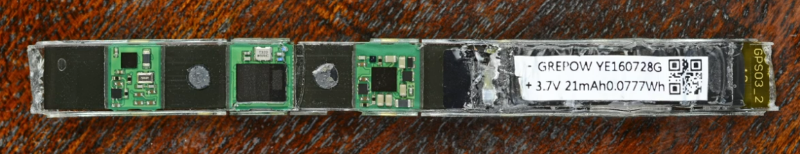
These smart rings would also contain curved batteries in order to fit the finger. In the end I managed to source these 18mAh batteries from Alibaba. Although their curve radius was not as tight as I would like in order to fit her smaller fingers, these were the best off the shelf I could find. Plus, I also learnt that there is an entire industry that makes custom curved batteries of different angles and capacity.
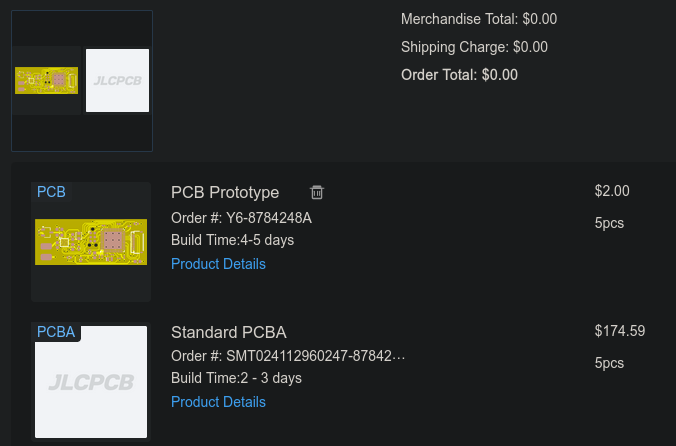
Later I found that making flex PCBs were prohibitively more expensive. This is because manufacturers would need to make use of custom fixtures to hold the PCB in place for assembly. Overall it meant that the cost to make one is about twice that of a normal PCB.
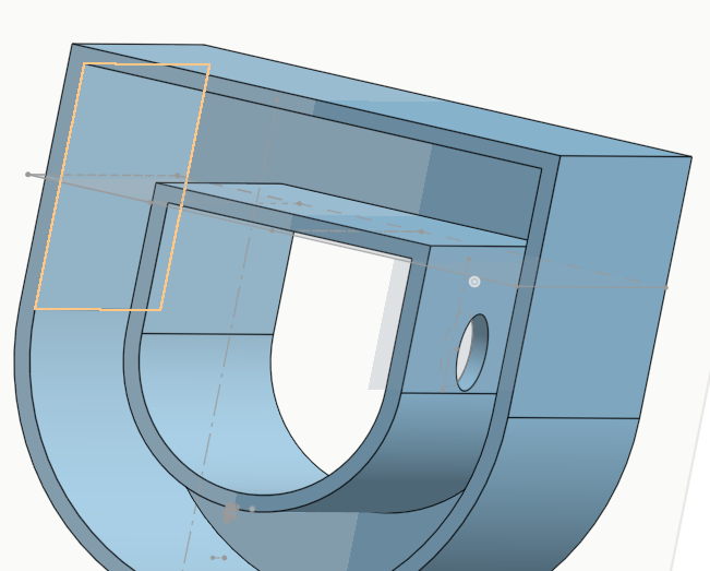
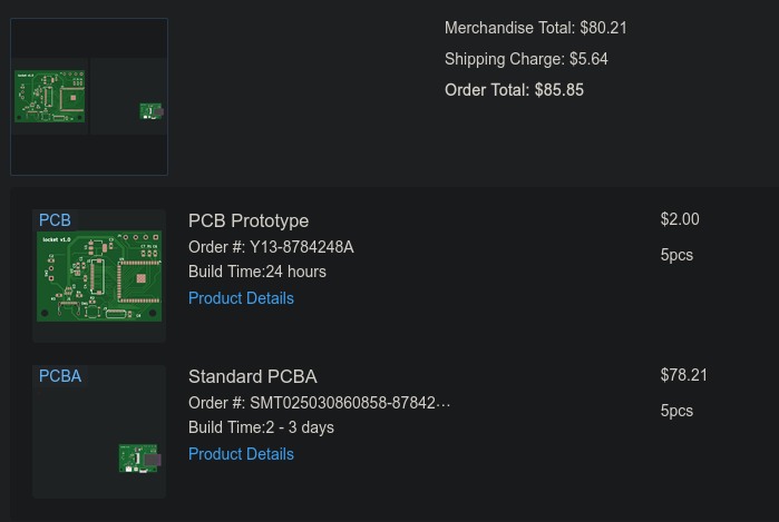 In the end, I went with the standard fixed PCBs, which quickly put an end to my dreams of making a completely ring-shaped ring. Another issue independent of the ringness is how to assemble all the components in a simple manner. For commercial smart rings these were often shaped and then encased in resin. This is a plausible option given that resin printers, UV curers are quite consumer friendly. I decided that this was not the path I wanted to take for now, and went with a lidded design, turning my ring into yet another electronics box.
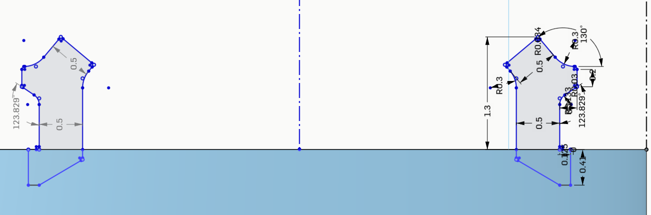
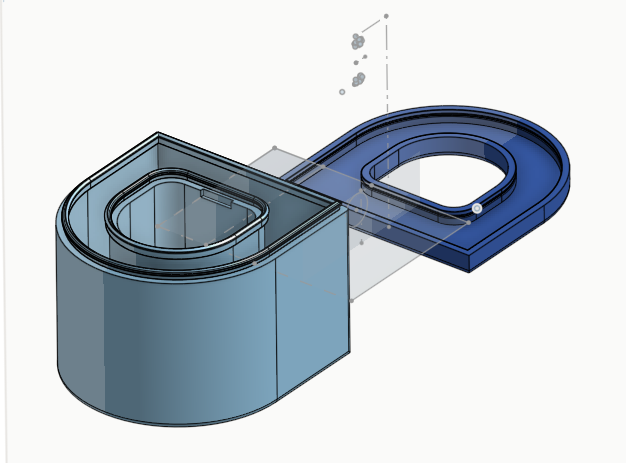 Also my first time doing any CAD, I went with
onshape for their accessible web interface. One of the main issues is designing the closing latch. Following this succinct
tutorial with some guesswork helped me to create a passable annular joint for the lid.
Also my first time doing any CAD, I went with
onshape for their accessible web interface. One of the main issues is designing the closing latch. Following this succinct
tutorial with some guesswork helped me to create a passable annular joint for the lid.
 Another aspect of the design is figuring out where and how to charge the battery without having to remove the whole thing. The straight edges arising from the curved part was for this purpose. I cut a hole in order to fit a tiny magnetic charging connector.
# PCB
This would be my first time designing a custom PCB. From my earlier requirements, I decided to use a STM32WB series MCU which had bluetooth capabilities for remote control. This may have also been partly motivated by the great tutorial series by Phil over on Phil’s lab. He provides a detailed walkthrough of the necessary components required to bring up the chip such as the power supplies, crystal oscillator and RF impedance matching circuit. His videos really allowed me to get the board right the first try.
One of the main challenges of this board was the battery charging circuit. A charge controller which provides a safe charging voltage and current. A battery monitor to prevent over and under-discharge of the battery during operation. A way to source power from the charger instead of the battery during charging. This is greatly simplified by a multitude of ICs that offer a single package for everything. However, for the battery specification that I required, there was no such magic chip.
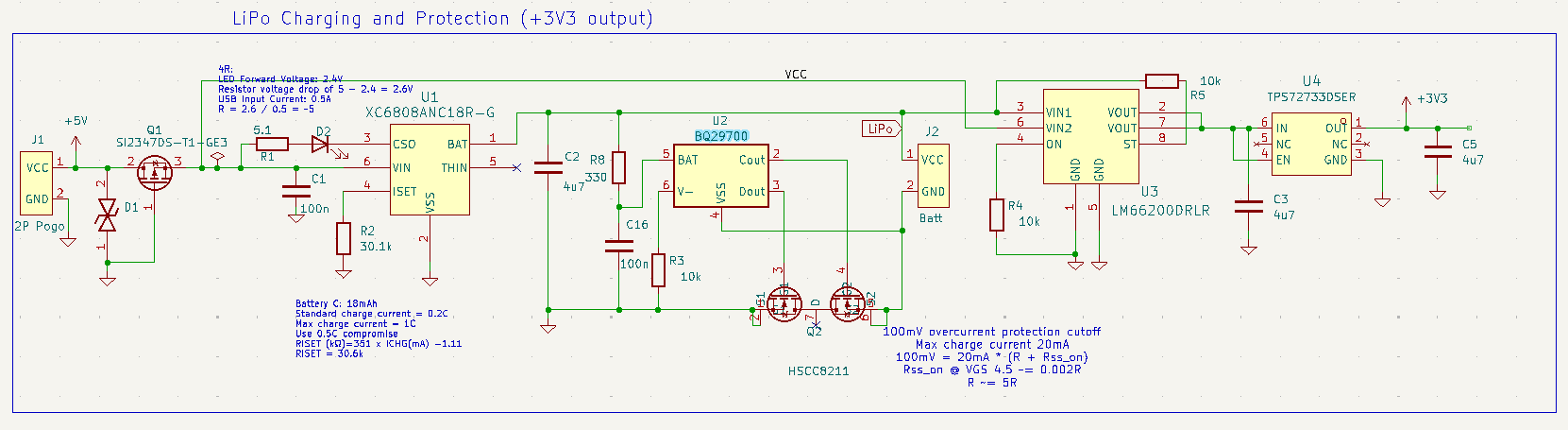 The charging schematic focused on getting close to the 1C charge rating for the battery. Please @ me if you notice any safety issues besides eye strain from the charging LED. (aside: for some reason I found that the over discharge protection does not seem to work)
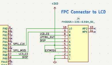 The display was simple enough to interface with. The peculiar thing is the LPTIM1_OUT signal to the MCU, which provided the minimum 1hz wave to refresh the memory display bits.
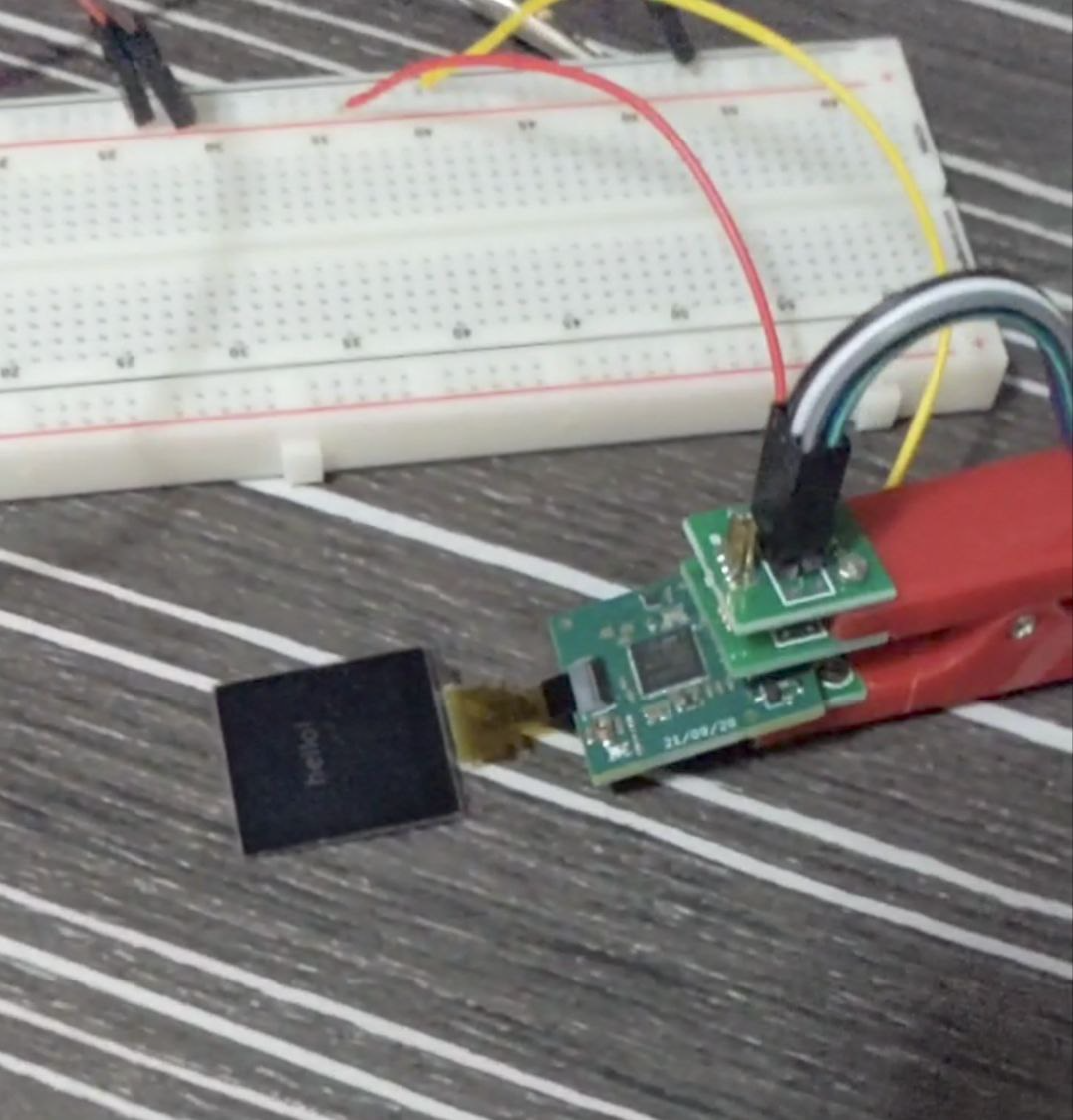 The programming setup is a SWD pogo clip.
# Regrets
I rushed the project as other parts of the proposal started to pile up. Here is a list of improvements I would have done. Either way, I learnt a lot during this project and its a testament to what you can do with a little will and too much youtube.
# Low power mode
Earlier I showed the use of LPTIM for generating the square wave. I had low power consumption in mind when deciding on that. From my early plans, I also hinted at finding a way to detect when the ring is worn. This would have allowed the STM32 to stay in sleep while there was no interaction.
One complication is the different low power modes available. These are quite well documented with the shutdown mode being the best in terms of power consumption.
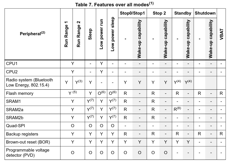 In practice, its likely Standby which one can reasonably hope to stay in.
Some ways I thought to achieve this were:
- Capacitive touch sensor. The STM32 has a few pins dedicated for its touch sensing controller. Soldering a large copper strip would allow wake up from low power sleep mode only.
- Gyroscope accelerometer combo. A classic option that would not be able to detect when ring is worn, but at least it could still be used to tell when it has been put down.
- Here some chips even allow for wake up from the RF system. The STM32WB55 that I went with did not support this (why did I not just use a different chip?????? I don’t know).
In the end I made the genius decision to do none of them. I can’t remember why, but it made it impractical, needing a new charge (sometimes from a portable charger) before being able to showcase it’s functionalities.
# Flex design
For it to be actually wearable I believe one cannot escape flex PCBs. This could itself bring about an entire new host of mechanical strain issues. Furthermore, the resin encasement would probably mean the whole thing became e-waste once the battery died. However, such a design would also likely require an onboard chip antenna, something I did not know about.